



DO-297 Introduction – Integrated Modular Avionics
Read Excerpt Below, or Click Here To Download Full 10-20 Page Paper
This DO-297 Whitepaper on Integrated Modular Avionics (IMA). Provides basic avionics IMA facts and IMA certification aspects per DO-178C. Further, since IMA is the future of many systems as they move on from traditional federated (standalone) avionics, whitepaper also provides information to help build successful DO297 IMA avionics.
DO-297’s title readily misleads new avionics engineers: “Integrated Modular Avionics (IMA) Development Guidance and Certification Considerations”. Perhaps, DO-297 has misled you too. Here is a quick quiz to determine if you have some basic IMA knowledge:
- T / F: Most of today’s avionics are “integrated” and “modular”.
- T / F: DO-297 mostly invokes processes similar to DO-17.
- T / F: For IMA components, DO-297 replaces DO-178C and DO-254.
- T / F: Partitioning and Health Monitoring are fundamental to
DO-297. - T / F: IMA systems require their own unique safety assessment
processes and results - T / F: IMA activities must consider the software, hardware, system
and aircraft as part of an interoperable whole ecosystem
If you are confident you know all the above answers and can explain your rationale, then some of the information in this whitepaper will be easy for you. Otherwise, this whitepaper will hopefully explain the answers plus many more.
First, aren’t all avionics systems “integrated”? Well, yes to some degree; many avionics systems in fact use outputs from other systems while sending their own outputs to yet other systems. But does this simple I/O constitute true integration? Consider a basic can-opener: it can probably open most types of cans and operates in different environments with different users, all while maintaining the ability to open cans. Yet it is neither “integrated” or “modular”: the can-opener has no affiliation with a particular can and is not provided in modules or pieces. In fact a can-opener is a standalone “system” which can be manual or electric. In avionics, we call such standalone systems “federated” and federated systems comprise traditional avionics most commonly in use today.
Integrated Modular Avionics (IMA) vs Real Life…
Modern CPU architecture, materials and IC design have provided computer platforms that can execute multiple applications with real-time precision. Furthermore, the need exists to have scalable platforms which can more readily add or replace hardware/software items while minimizing re-certification when doing so. Integrated Modular Avionics (IMA) is targeted to these computer platforms which makes possible avionics software that contains several applications executing in parallel using a core set of hardware software items comprising the platform basis. These systems include vast stores of memory and integrated peripherals; a good example of this type of platform you routinely carry in your pocket as a cell phone. (Whether or not it is still a “phone” is debatible.)
The cell phone has evolved from the “chocolate bar” style with annoyingly loud ringtones and haptic pushbuttons used to initiate a voice call. (In fact, the voice call was about the extent of the functionality in early cell phones.) Today the cell phone is a handheld computer that is used to host sophisticated gaming interactions, browse the web, securely access bank accounts, record video and pictures, GPS mapping/location and applications that can be used to attend video meetings, order a meal, board a flight or secure a ride across town. Thus, today’s smart phone exemplifies IMA which is now deployed in aircraft but requires special certification guidance; this is where DO-297 applies.
However, every user’s experience is that from time to time you need to “power cycle” this phone, usually AFTER it has stopped functioning. This occurs for a variety of reasons and the condition can be resolved by simply restarting the device. For this primitive example the issue is most likely that a software “error” has occurred. (Remember the days of the “blue screen of death” on your PC/Laptop? All that was needed was a press of the “big red button” to resolve the issue. That was most likely a software “error”!) Using an Integrated Modular Avionics system based on a cell phone or laptop, which may require an untimely reset, is not a good choice in avionics design; the reason is obvious.
Note that the word error above is in quotes and is intended to suggest that system/hardware errors often are perceived as software errors. A software error can occur due to a hardware-based anomaly during CPU execution of machine instructions. If the CPU executes a machine instruction incorrectly or as not intended, the software likely responds with non-deterministic logic. (Modern CPUs execute billions of machine instructions every second.) Standards such as DO-178C utilize methods to mitigate these un-intended consequences within the context of the application instructions. While DO-297 presents mitigation strategies and design approaches for errors that can occur outside the realm of the application software. For example, an application failing if a shared resource (RAM) is not handled predictably. A data transfer on the CPU bus has a latent bit error resulting in another application “invading” the RAM space where the application is executing.
DO-297 presents guidelines and design patterns for systems that use IMA and can host multiple applications and system functions in a single LRU (Line Replaceable Unit) which satisfy the safety guidelines describe in ARP4754/4761.
The Old Days.
You now know the “Old Days” of technology refer to any time prior to last year. In the Very Old Days (moon landings, space shuttles, commercial jets with four engines) there was not a concept of IMA. In these dark and forgotten times one single LRU (CPU plus peripherals) hosted one system application and one system function. If you go far back in the time continuum the LRU was generally a CPU card hosted inside a backplane bus-based chassis (VME/PCI) which contained application specific circuit cards, i.e. an ADC card, a DAC card, Serial Communications etc. Each of these LRU’s, arranged in a federated architecture (Figure 2), required a specific range of power, as well as custom integrated software for that specific application. While these systems are not flawed or unsafe they do increase the weight of the aircraft and reduce efficiency as engine power (fuel) is diverted to power needed to support all the LRUs onboard. In addition, there are measurable costs to support all the LRU hardware and software.
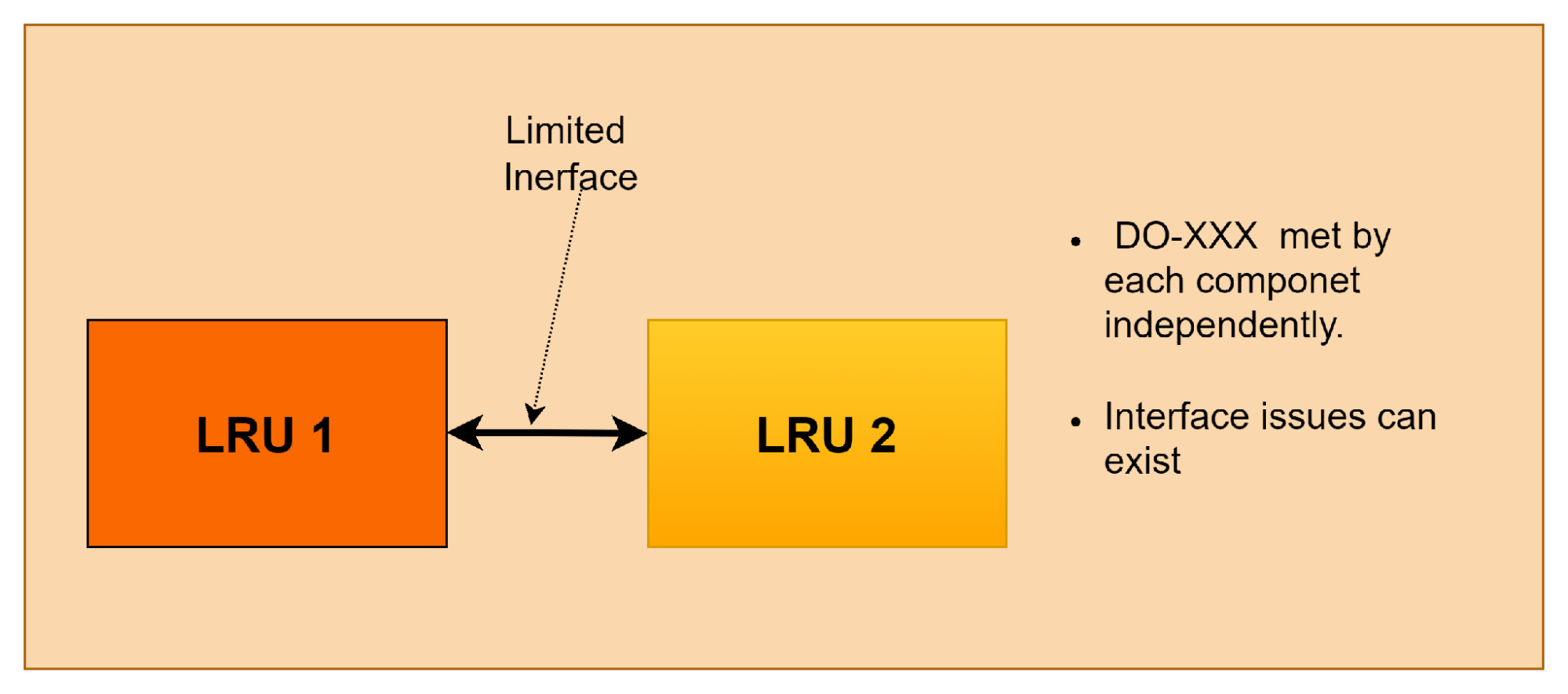 Figure 2: Federated System Example
IMA with DO-297 Today.
IMA models have evolved based on sophisticated, more complex and reduced power Integrated Circuits (IC). i.e. a Micro Controller Unit (MCU). An MCU, sometimes referred to as a System On a Chip (SOC), can contain multiple CPU cores (sometimes several cores!), it may contain an FPGA and requires significantly reduced power when compared to previous CPUs. SOCs and MCUs provide integrated peripherals to handle functions such as I/O, ADC, Serial/IP/I2C/SPI based communications, as well as single event detection. (some MCUs can correct single event errors in real time!) The guidelines in DO-297 divide the IMA System Development Process into three focused subsystem development processes:
- System Development
- Platform Development
- Hosted Application Development
These processes and tasks suggested for implementation are the focus of this whitepaper. The processes are focused on design of the subsystems and their interrelation to each other as described in the architecture diagram below. Where a platform (also considered a module) presents general purpose modules and software components to hosted applications which may have application specific modules and components.
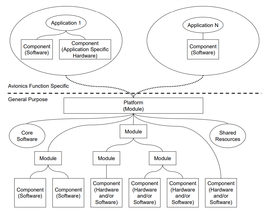 FIGURE 3: DO-297 Sample of an IMA System
Additionally, DO-297 provides guidance to interconnect multiple IMA systems into a distributed platform. This brings avionics systems into the realm of backend data servers, akin to systems that power the internet.
DO-297 guidelines include a certification process to obtain incremental acceptance and certification credit for an IMA platform and is organized into six tasks, with 54 total objectives:
Task 1: Module acceptance
Task 2: Application software or hardware acceptance
Task 3: IMA system acceptance
Task 4: Aircraft integration of IMA System – includes Verification and Validation.
Task 5: Change of Module or Applications
Task 6: Reuse of Modules or Applications
Systems developed via DO-297 have these guidelines as one piece of the avionics ecosystems: it is preceded by, and must consider, the safety assessment which is used to help define aircraft/system architecture, and aircraft/system safety requirements. In turn, it is paralleled by DO-178C and DO-254 which are the certification basis of the platform hardware and application software. You cannot certify an IMA system without using DO-254 and DO-178C in the development of the subsystems which are all further qualified by DO-160. A refined view of the relevant guidelines is depicted here:
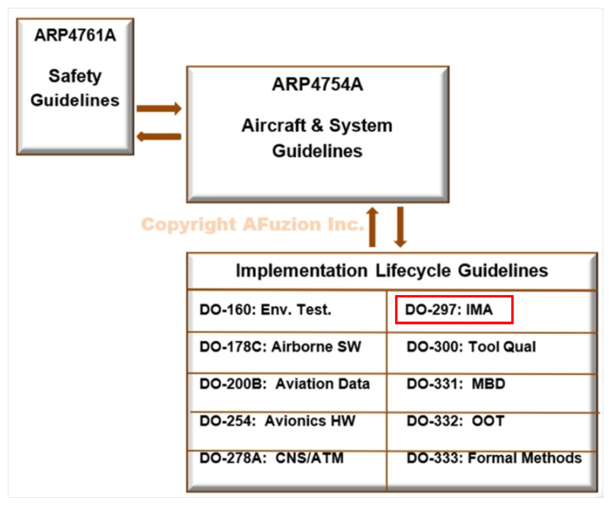
FIGURE 4: Avionics Ecosystem
DO-297 and IMA Overview:
DO-297 is intended to be used by the international aviation community and as an aid in such use references to specific national regulations and procedures are minimized. The document uses generic terms are used such as “certification authority” to mean the organization or person granting approval on behalf of the country responsible for aircraft and/or engine certification. DO-297 IMA guidance is not mandated by law, but it represents a consensus of the aviation community and avoids the use of the word “shall”. However, it does use the word “should” to describe methods required to adhere to DO-297.
DO-297 for Integrated Modular Avionics is structured to introduce the reader to IMA and highlight the attributes of IMA that affect the development, acceptance, and installation approval of IMA systems on aircraft, it consists of the following chapters:
- Chapter 1 of DO-297 gives the reader an overview of this document.
- Chapter 2 of DO-297 introduces the concept of IMA and highlights the system, hardware, and software characteristics.
- Chapter 3 of DO-297 provides a description of IMA-specific development and integration guidelines.
- Chapter 4 of DO-297 provides guidelines for the acceptance of IMA and describes the relationship to the approval of the installed IMA system.
- Chapter 5 of DO-297 describes integral processes for IMA development.
- Chapter 6 of DO-297 includes guidelines for continued airworthiness of IMA systems.
The figure below shows an example of a typical design highlighting potential shared resources. The shaded areas identify the modules that may be shared.
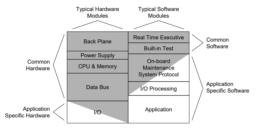 Common Example of IMA Design per DO-297
IMA / DO297 Health Monitoring and Fault Management (HM/FM)
Health monitoring and fault management (HM/FM) functions deserve special attention due to the integration of multiple applications and resource sharing. Adherence to DO-297 requires that IMA systems manage the following functions:
- Platform faults
- Hardware failures
- Partitioning violations
- Errors and anomalous behavior of hosted applications
- Common mode faults
- Cascading failures.
The methods used to manage platform faults are independent of the hosted applications, for obvious reasons. Fault management consists of detecting faults, failures and errors, correctly identifying them when they occur and performing the appropriate response.
DO-297 specifies that health monitoring and fault management (HM/FM) functions should be provided with recognition that the IMA platform may support a collection of diverse aircraft functions. The IMA platform should address both operational and maintenance concerns. Strategies for HM/FM development may include:
- Identification of components and aspects to be monitored.
- Health determination of each application.
- Determination of the health of the IMA system as a whole.
- Response to each type of failure or anomalous behavior.
- Flight crew annunciation and messaging.
- Control of maintenance actions and reporting.
- Redundancy management.
- Single event upsets.
Health monitoring is that part of the IMA platform responsible for detecting, isolating, containing, and reporting failures that could adversely affect applications. This function should detect faults in the shared resources used by the hosted applications, such as memory dedicated to an application partition that is monitored by the IMA platform rather than the application. The system architecture should be designed to promote the detection of faults at the lowest possible architectural level, this reduces the potential for ambiguity. Do-297 notes that faults are generally detected by their symptoms, potentially leaving some ambiguity about which component actually failed. The smaller the ambiguity group is for a fault the easier it is to define policies for resolving it safely.
Robust Partitioning for IMA per DO-297
Robust partitioning should support the cooperative coexistence of core software and applications hosted on a processor which use shared resources, while assuring unauthorized or unintended interference is prevented. Robust partitioning should meet the following information guidelines in DO-248/ED-94:
- A software partition should not be allowed to contaminate the code, I/O, or data storage areas of another partition.
- A software partition should be allowed to consume shared processor resources only during its allocated time.
- A software partition should be allowed to consume only its allocation of shared I/O resources.
- Failures of hardware unique to a software partition should not cause adverse effects on other software partitions.
IMA Terminology
- Aircraft Function – The capability of the aircraft that may be provided by the hardware and software of the systems on the aircraft. This comes from ARP4761A per the FHA
- Application – Software and/or application-specific hardware with defined interfaces, when integrated with a Platform, performs a function.
- Component – Self-contained HW/SW/DB part under configuration control.
- Core Software – OS and support software to manage resources, allow applications to execute. Necessary component of a Platform.
- IMA Platform per DO-297 – Module or modules, including Core Software that manages resources sufficient to support at least 1 application. Does not by itself provide any aircraft functionality. May be accepted independently of hosted applications.
- IMA Interoperability – The capability of several integrated modules to operate together to accomplish a specific goal or function. This requires defined interface boundaries between the modules and allows the use of other interoperable components.
- IMA System – Consists of an IMA Platform and a defined set of hosted applications.
- IMA Module – Collection of components
- IMA Partitioning – An architectural technique to provide the necessary separation and independence of functions or applications to ensure that only intended coupling occurs. The mechanisms for providing the protection in an IMA platform are specified to a required level of integrity.
- Resource – Any object (processor, memory, software, data, etc.) or component used by an IMA platform or application. A resource may be shared by multiple applications or dedicated to a specific application. A resource may be physical (a hardware device) or logical (a piece of information).
- Reusable – The design assurance data of previously accepted modules and applications may be used in a subsequent aircraft system design with a reduced need for redesign or additional acceptance.
Additional terms and DO-297 / IMA details are provided in the remaining 20 pages (just request free download) of this AFuzion technical whitepaper and also covered in AFuzion’s DO-297 Training HERE.
Key IMA Platform Characteristics:
The key characteristics of IMA platforms and hosted applications influence the IMA system architecture, the detailed system design, and, ultimately, the IMA platform and system acceptance process. Two primary building blocks of an IMA system are the platform and the hosted applications. The key characteristics for the IMA platform:
- Resources of the IMA platform are shared by multiple applications.
- An IMA platform provides robust partitioning of shared resources
- An IMA platform only allows hosted applications to interact with the platform and other hosted applications through well-defined interfaces.
- Shared IMA platform resources are configurable. (Integration)
The key characteristics for the IMA hosted applications:
- An application may be designed independent of other applications and obtain incremental acceptance on the IMA platform independently of other applications.
- Applications can be integrated onto a platform without unintended interactions with other hosted applications.
- Applications may be reusable.
- Applications are independently modifiable.
Key Stakeholders (Roles)
The assignment of roles and responsibilities is necessary and should address the entire IMA system life cycle from conceptual design to retirement. Assignments may be based on the underlying IMA system architecture and should include the responsibility for selecting and providing tools. The responsibility for certain activities, data generation, and for demonstrating compliance should be coordinated, communicated, and resolved among the stakeholders as early as possible in the program. Identifying what needs to be done and by which role reduces the probability that an integration input is missed, such as development of a Board Support Package (BSP) to port an OS to target hardware.
Key Stakeholders in building an IMA system:
- RTOS Developer / Platform Supplier – Provides the processing hardware and software resources, including Core Software.
- Application Supplier – Develops and verifies the hosted application.
- System Integrator – Integrates the Platform and the hosted applications to form the IMA system.
- Certification Authority – Review Data and Pass Judgement.
- Maintenance Organization – follows the approved procedures received from the certification applicant to keep the IMA system and the aircraft in an airworthy condition.
Free: Download Remaining 10+ Page Paper Here
DO-297 Introduction – Integrated Modular Avionics
Read Excerpt Below, or Click Here To Download Full 10-20 Page Paper
This DO-297 Whitepaper on Integrated Modular Avionics (IMA). Provides basic avionics IMA facts and IMA certification aspects per DO-178C. Further, since IMA is the future of many systems as they move on from traditional federated (standalone) avionics, whitepaper also provides information to help build successful DO297 IMA avionics.
DO-297’s title readily misleads new avionics engineers: “Integrated Modular Avionics (IMA) Development Guidance and Certification Considerations”. Perhaps, DO-297 has misled you too. Here is a quick quiz to determine if you have some basic IMA knowledge:
- T / F: Most of today’s avionics are “integrated” and “modular”.
- T / F: DO-297 mostly invokes processes similar to DO-17.
- T / F: For IMA components, DO-297 replaces DO-178C and DO-254.
- T / F: Partitioning and Health Monitoring are fundamental to
DO-297. - T / F: IMA systems require their own unique safety assessment
processes and results - T / F: IMA activities must consider the software, hardware, system
and aircraft as part of an interoperable whole ecosystem
If you are confident you know all the above answers and can explain your rationale, then some of the information in this whitepaper will be easy for you. Otherwise, this whitepaper will hopefully explain the answers plus many more.
First, aren’t all avionics systems “integrated”? Well, yes to some degree; many avionics systems in fact use outputs from other systems while sending their own outputs to yet other systems. But does this simple I/O constitute true integration? Consider a basic can-opener: it can probably open most types of cans and operates in different environments with different users, all while maintaining the ability to open cans. Yet it is neither “integrated” or “modular”: the can-opener has no affiliation with a particular can and is not provided in modules or pieces. In fact a can-opener is a standalone “system” which can be manual or electric. In avionics, we call such standalone systems “federated” and federated systems comprise traditional avionics most commonly in use today.
Free: Download Remaining 10+ Page Paper Here